Once again, it’s the time of year when we issue a new release of OrcaFlex. This year, for the first time since 2006, sees an increment to the major version number! We are delighted to announce the 2015 release of OrcaFlex, version 10.0.
The software was finalised and built on 20th October. We are currently preparing the installation program, and will then dispatch the software. All clients with up-to-date MUS contracts should receive the new version early in November.
Version 10.0 introduces much new functionality, including:
- Frequency domain dynamic analysis.
- Generalised connection ordering. It is now possible to connect lines directly to other lines and to form chains of connections.
- Slamming and water exit loads can be applied to lines.
- Contact stiffness may now be nonlinear.
These are the most significant developments. As always there are a great many more enhancements which are documented in the What’s New topic for 10.0.
What follows is a brief introduction to each of the new features that we consider to be of most significance.
Frequency domain dynamic analysis
The earliest versions of OrcaFlex, from version 1 to 8, offered dynamic analysis by explicit time domain integration. Version 9 introduced an implicit time domain solver. And now version 10 introduces a third dynamic solver, performing frequency domain analysis.
The great benefit of frequency domain analysis is that it is much faster than time domain analysis. However, the flip side of this is that frequency domain analysis is a linear analysis. So, for systems that have nonlinearity, frequency domain analysis is less accurate than time domain analysis, which is fully nonlinear. As a consequence, whilst the performance benefits of frequency domain are very appealing, for many classes of system or analysis it may not be appropriate to obtain a linear solution. However, when linear analysis is applicable, a frequency domain solver is very effective since it is typically one or two orders of magnitude faster than time domain analysis.
Input data
Introducing a frequency domain solver to OrcaFlex required changes to a great many parts of the code. However, we have strived to minimise changes to the user interface. Our goal has been that you should be able to build one model, and then analyse it in either time domain or frequency domain at the flick of a switch.
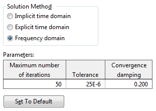
So, what does that switch look like? The General data form has been adapted a little and on the Dynamics page the Solution Method allows you to select from the three available dynamics solvers.
Selecting frequency domain analysis does result in some changes to the available data. For instance, simulation stage and duration data are no longer available. That is because they have no meaning in the context of a frequency domain analysis. Likewise, data that refers to simulation stages are no longer available, for instance release stage, winch control data that is specified by stage, etc. If you switch back to a time domain solution method, then all of this data is relevant again, and so it all becomes available again.
Results
Another area of the program that has been changed for frequency domain is the results presentation. Again, nothing too drastic, but changes are essential because many of the results offered for time domain analysis are meaningless for frequency domain. For instance, time history results are not available for frequency domain analyses. A frequency domain analysis is a stochastic analysis, and so OrcaFlex reports statistical and spectral results: standard deviation, extreme value statistics, spectral density, spectral moments, etc.
In addition to results for single analyses, the fatigue analysis has been developed to work with the frequency domain solver. Because the frequency domain solver output is spectral in nature, spectral fatigue analysis is the appropriate method. OrcaFlex can carry out a spectral fatigue analysis based on frequency domain simulations for each sea state in the scatter diagram. The cycle counting is performed using either the Rayleigh or Dirlik methods. These spectral methods are very much faster than rainflow fatigue analyses.
Linearisation
As mentioned above, frequency domain analysis is by necessity linear. How then does OrcaFlex deal with any nonlinearities that are present in the model?
In the main, the system is linearised using the tangent stiffness, or tangent damping in the case of damping loads. Special treatment is reserved for drag which is linearised using the minimum mean square error method. More details on the subject of linearisation can be found in the frequency domain documentation.
Unsupported features
Not all OrcaFlex features are compatible with frequency domain analysis. For example, time varying loading is simply not compatible with frequency domain analysis. OrcaFlex reports an error if you attempt to analyse a model that uses such a feature.
In addition to features that are not compatible with frequency domain analysis, some features are not yet supported by the OrcaFlex frequency domain solver. These as yet unsupported features include, but are not limited to:
- Line stiffeners.
- Line contact containment (line contact without containment is supported).
- Calculated vessels.
- Sea state RAOs.
- Wind loading.
- Variable drag coefficients.
Again, if you attempt to use such features in a frequency domain analysis, OrcaFlex reports an error.
Future developments
We are very excited about the possibilities afforded by the new frequency domain solver. But we are also aware that it can be improved in a number of ways from its current form.
In future releases we will add support for at least some of the currently unsupported features. We will prioritise this in the usual way by weighing up the benefit to users with the complexity of implementation. So, if you have strong feelings that certain additional features should be supported by the frequency domain solver, please let us know.
We are also aware that there are a number of enhancements that can be made to facilitate frequency domain mooring analysis and we are keen to enable such analyses to be performed efficiently using OrcaFlex. Again, if this is an area of interest for you, and you have opinions on how you feel we should develop the program, we do encourage feedback.
Generalised connection ordering
I’m going to wallow in a little history here, hopefully to explain and give some insight into why OrcaFlex has for so long had frustrating limitations in the type of boundary conditions that it supports. Feel free to skip over this historical excursion to the modern day details found five paragraphs below!
As mentioned earlier, dynamic analysis in the earliest versions of OrcaFlex used an explicit solver. For an FE code like OrcaFlex, an explicit solver is much simpler to implement than an implicit solver, or indeed a frequency domain solver. For instance, explicit solvers do not require system-wide mass, damping and stiffness matrices to be formed. The integration step can be performed independently for each rigid body in the system, e.g. each vessel, buoy, node in OrcaFlex terminology.
This simplicity led to a number of implementation decisions that placed limitations on the type of boundary conditions that the program accepted. Experienced OrcaFlex users will be all too familiar with these limitations. Buoys could be connected to other objects. Other objects could be connected to buoys. But a single buoy could not be both connected to another object, and have other objects connected to it. Lines could be connected to other objects, but not connected directly to other lines. Invariably workarounds could be found, typically involving intermediate buoys used as connector objects, but these workarounds were tedious.
When we added the implicit solver, we were forced to face up to forming system-wide mass, damping and stiffness matrices. So, we did this, and this development paved the way to a better internal architecture. We fitted the new implicit solver around the original explicit solver, sharing most of the code, but not fundamentally re-writing the explicit solver code. Consequently, OrcaFlex was still subject to the same limitations as before. More recently we came to develop a frequency domain solver. We decided this time that instead of trying to fit this new solver around the existing solvers, we would re-implement the low-level coordinate handling architecture to support all of our solvers in a unified manner.
This has been a very ambitious and challenging development, but ultimately a very rewarding one. As of version 10.0, all the OrcaFlex solvers use the new unified architecture. Not only can we now remove the limitations mentioned above, but the code will now enable future development to be carried out more quickly and more safely. Furthermore, this new unified coordinate manager will enable many interesting future developments that we otherwise could not have contemplated.
OK, that’s enough history. What about the here and now? Well, as promised, OrcaFlex 10.0 removes limitations on the type of connections that can be made. Lines can be connected directly to other lines. Objects can be connected in sequences of arbitrary length. For instance a vessel can have a buoy connected to it, which in turn has lines connected to it.
Where, previously, the program would have forced you to create intermediate connecting buoys, in version 10.0 you can usually dispense with them. There is however one common exception to that statement. When connecting lines directly to lines, with non-zero connection stiffness, you would typically expect moments to be transferred from one line to the other. In order for OrcaFlex to be able to transfer moments, the master line in the relationship must include torsional degrees of freedom. If the master line does not include torsion, moments are not transferred. Whilst it is simple enough to enable torsion on the master line, torsion lines do increase the simulation time. So if your analysis is particularly sensitive to runtime then it may be more effective to use an intermediate connector buoy which will allow you to exclude torsional degrees of freedom from the lines.
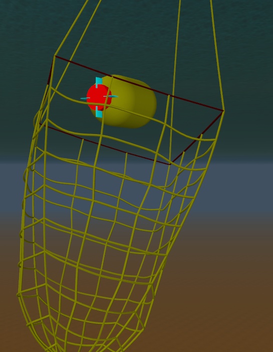
As an example of the more exotic models that can be built more easily, here’s a screenshot of a net built with line elements, but without any connecting buoys.
This development is just the beginning of what we plan to do with the new functionality available to us. In future releases we plan to provide much more general constraint modelling, for instance hinges and articulations, constraints for individual degrees of freedom, etc.
The one downside of all these changes is that the explicit solver is slower than in previous versions. This has come about because we have re-implemented the explicit solver on top of the new unified coordinate handling code. In a sense, this can be seen as the cost of the extra generality. The removal of connection ordering limitations is extended to the explicit solver just as it is to the other solvers. But this added flexibility costs in simulation runtime. We judged that the explicit solver is used so infrequently nowadays that this trade-off was worthwhile.
Slamming and water exit loads applied to lines
Previous versions of OrcaFlex offer slamming loads for 6D Buoy objects. For some applications it would be more convenient for the slamming loads to be applied to Line objects. One common scenario where this is so is the modelling of jumper installation. Typically the jumper would be modelled with pre-bend to capture the jumper’s geometry. In previous versions, slamming loads could only be applied by way of 6D Buoys attached at various points along the jumper line. Quite possible to do, but rather inconvenient and tedious.
Version 10.0 now admits slamming and water exit loads applied directly to lines. The model is the same as previously used for 6D Buoys, so all you need to do is apply the data to the Line Type object rather than the 6D Buoy object. The new data looks like this:
Just as for 6D Buoys, the added mass data can be specified to vary with submergence. And separate slamming entry and exit data can be provided. Details of the theory used are provided in the OrcaFlex documentation for slamming.
Nonlinear contact stiffness
Contact stiffness for seabeds, elastic solids, line contact and supports can now be specified to be nonlinear elastic in addition to linear elastic.
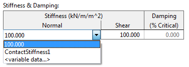
This development is pretty straightforward to explain. Where in previous versions you would specify a single linear contact stiffness value, you can now, optionally, specify a piece-wise linear table. This is done using the variable data framework, and as an example this is what the seabed stiffness data looks like in version 10.0:
The same approach is used for elastic solids, line contact and supports.


