Mooring line fatigue damage normally considers only tension load cycles. However, sometimes the mooring chain immediately adjacent to the fairlead (the ‘Top Chain’) can experience significant in-plane and out-of-plane bending which causes additional fatigue damage.
BV guidance note Fatigue of Top Chain of Mooring Lines due to In-plane and Out-of-plane Bendings, [NI 604 DT R00 E, Aug-14], (‘BV note’) describes a Top Chain fatigue damage assessment procedure which includes both tension and bending. Here we describe how to derive the necessary OrcaFlex results to use with the procedure outlined in the BV note.
SUMMARY OF CALCULATION METHODS
The BV method relies on post-processing pin-connected time histories of line tension and Top Chain Angle. These results come from a time domain analysis such as OrcaFlex would perform. Full details are in Section 2 of the BV note.
In the absence of a Fairlead Chain Stopper (FCS), the Top Chain Angle is the angle between the chain and the vessel. If an FCS is present, Top Chain Angle is the angle between the chain and the local axis of the FCS.
The effect of an FCS may be accounted for in one of two ways: (i) Exclude the FCS from the mooring analysis, but include its effect when performing the post-processing – this is the main approach presented in the BV note (see Section 2, 1.2 therein for more details). (ii) Include the FCS directly in the mooring analysis – see FCS Rotation below.
Once the Top Chain Angle is known, the bending in the Top Chain is calculated from the chain “interlink stiffness”. Again, the BV note calls for, and presents a methodology for, post-processing to find the Top Chain bend moments. However, Chain Interlink Stiffness below gives details on how to include interlink stiffness directly in the OrcaFlex mooring analysis.
Finally, stress ranges and consequent fatigue damage in the Top Chain can be found from the tension and bending moments. The BV note outlines these calculations in some detail. Determination of stress ranges can’t be done in OrcaFlex (unless using the “Externally calculated stress” damage calculation option in OrcaFlex’s fatigue post-processing) and requires further post-processing.
SUMMARY OF ORCAFLEX USE IN THIS CONTEXT
Here we summarise how OrcaFlex can provide the necessary angle results (tensions are also needed, but are straightforward to obtain) to feed into the pin-ended post-processing methodology presented by BV. We do not attempt to explain the BV post-processing methodology. We then briefly outline how to include a FCS and / or chain interlink stiffness directly in the OrcaFlex mooring analysis – note that such alternatives would need separate BV approval (Section 2, 1.1.4).
FATIGUE THROUGH POST-PROCESSING CALCULATION ONLY
The time domain mooring analysis should have pin-ended connections between the line and the vessel (BV Section 2, 1.1.3), and should exclude an FCS. Guidance on the sea-states to be considered is given (BV Section 2, 2.2.1 & 2.2.2), and sensitivity studies are also required (BV Section 2, 2.3).
Results include time histories of:
- tension at the fairlead,
- Top Chain angle relative to global (α in the BV note) for both in-plane and out-of-plane directions, and
- vessel rotation angle relative to global (β in the BV note) for both in-plane and out-of-plane directions.
The angles are illustrated below (Section 2, Fig 1 of the BV note):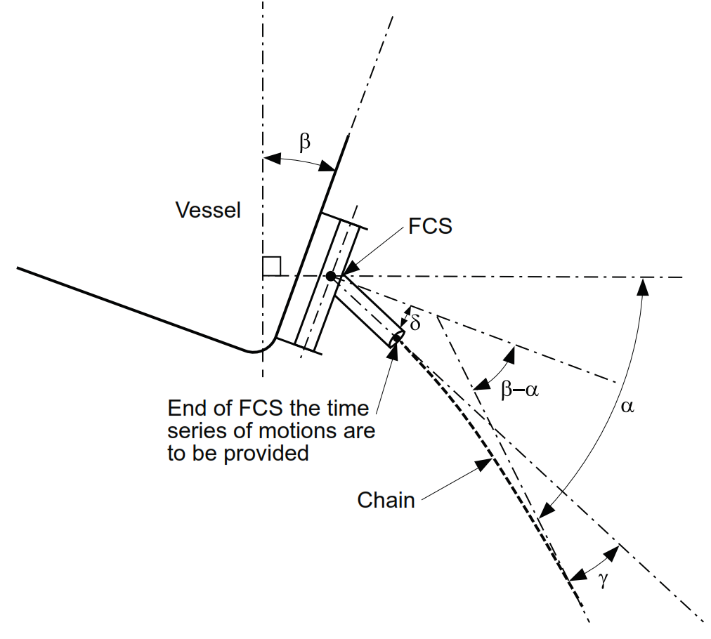
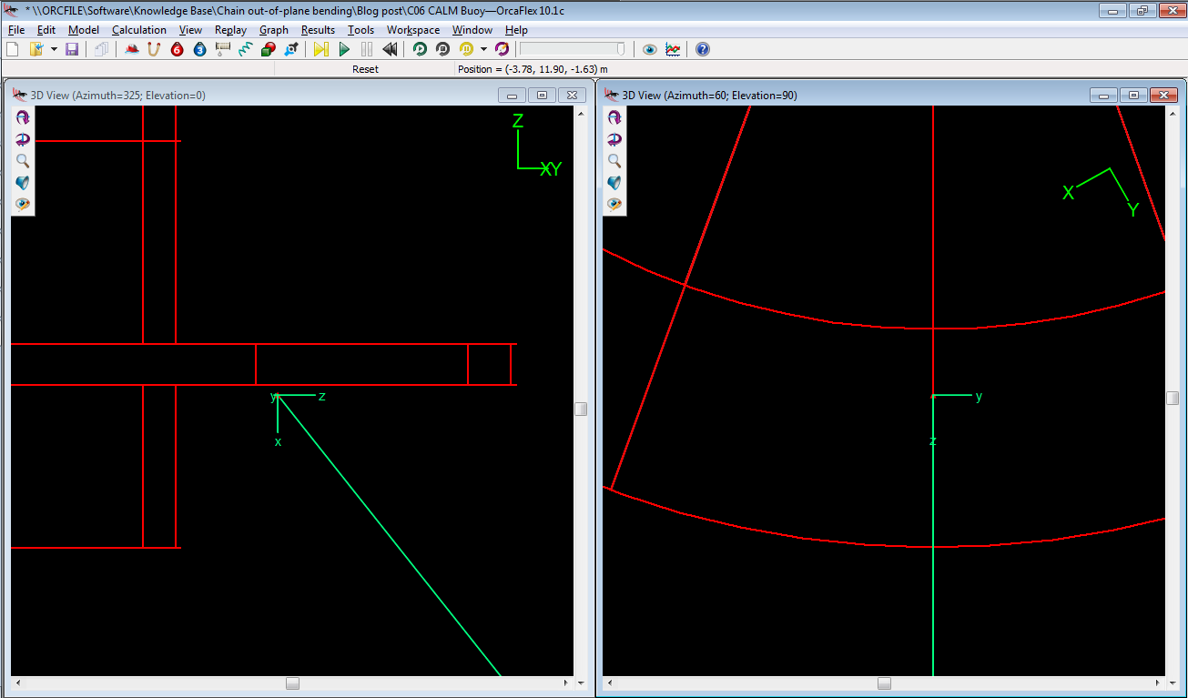
The BV methodology needs the relative angle (β – α), as show in the above figure. This angle represents the chain angle relative to the vessel’s local horizontal axis. This can be found by taking the OrcaFlex Ez-angle components at End A of the line, but only with the local end connection z-axis direction set to be horizontal relative to the vessel and aligned with the vertical plane of the mooring line. Then, the Ezx-angle and the Ezy-angle respectively give the in-plane and out-of-plane components of (β – α).
Time histories of these results are easily obtained from OrcaFlex simulations either using the GUI or any of the standard automation methods (OrcaFlex Spreadsheet, Python, Matlab or the API). The required configuration for the line end axes is shown in the following OrcaFlex screenshot:
MOORING ANALYSIS USING “ALTERNATIVE METHODOLOGIES”
To reduce the amount of post processing, there are two alternative methodologies which could be used. Such alternatives would need separate BV approval (Section 2, 1.1.4).
FCS Rotation
Here the FCS is included directly in the OrcaFlex model, so that its rotations are captured as part of the simulation.
This can be done using an OrcaFlex Constraint (OrcaFlex v10.1+) to connect a line to the vessel and setting the appropriate rotational degree of freedom to be ‘Free’. OrcaFlex Constraints don’t include friction, so the FCS bearing friction can be captured in one of two ways:
- by using non-linear rotational stiffness if you are comfortable that this will adequately represent the friction, or
- by applying a moment controlled by an external function. This can fully capture the frictional stick-slip behaviour of the FCS. We’ve done this and with good results, but it seems that small time steps are required during the simulation.
Chain Interlink Stiffness
Here the chain interlink stiffness is directly included in the OrcaFlex model by applying non-zero bending stiffness to a short section of the mooring line representing the Top Chain. Then the bending moments in the Top Chain are determined as part of the simulation.
Note that OrcaFlex calculates bending moment as M = EI.c (where M = bending moment, EI = bending stiffness, c = curvature). Care is needed to define a value of EI that gives the correct bending moment for a given chain interlink angle (αint from the BV Note). To achieve this, curvature must be related to the chain interlink angle. Assuming that each link remains straight (as shown in Section3, Figure 2 in the BV Note):

these terms can be related as c = αint / L, where L = chain link length and αint is in radians.
For systems without an FCS, the behaviour of the chain is then fully characterised in the OrcaFlex model. However, if an FCS is present, then the bending moments in the chain will not be correct unless the rotational behaviour of the FCS is also physically represented in the OrcaFlex model.
We hope that this post has been of some use for those studying the fatigue behaviour of mooring Top Chain. Please do not hesitate to comment or contact us if more information is needed.