
|
Shapes: Wire frame |
|
|
Shapes: Wire frame |
A wire frame shape has no physical effect on the model, and is used solely for drawing purposes.
Wire frame shapes have the following data:
This consists of three rotation angles, rotation 1, 2 and 3, defining the shape's orientation, $\Sxyz$, relative to the connection axes, $\Cxyz$. $\Sxyz$ is calculated by first aligning the shape with $\Cxyz$, such that $\Sxyz = \Cxyz$. Rotation 1 is applied about $\vec{S}_x (=\vec{C}_x)$, followed by rotation 2 about the new $\vec{S}_y$ direction, and finally rotation 3 about the new (and final) $\vec{S}_z$ direction.
The drawing data, represented by a set of vertices and either edges or panels, are used to draw the shape in both wire frame and, by default, shaded views (more elaborate imported 3D models may also be used).
The wire frame origin is defined relative to the shape axes $\Sxyz$, and the vertices are in turn defined by giving their coordinates relative to the wire frame origin.
Wire frame symmetry can be one of none, xz plane, yz plane or xz and yz planes. If wire frame symmetry is specified then the vertices, edges and panels are reflected in the specified symmetry plane or planes to generate additional vertices, edges and panels that are implied by the symmetry.
The wire frame type determines how the wire frame is specified:
Wire frame data can be imported from panel mesh files. When this is done, the data is imported into the OrcaFlex internal model data, and the wire frame type will be either edges or panels, depending on the choice made at the point of import.
| Note: | Importing wire frame data from panel mesh files performs a very similar function as using an external file as the wire frame type. The key difference is where the data for the panels resides. When importing, the data is brought in to the OrcaFlex model, and saved as part of that model. The connection with the panel mesh file is only needed at the point of import. When using an external file as the wire frame type, the panel mesh is read whenever OrcaFlex loads the model. |
| If the same wire frame data is used for many different model files, e.g. different load cases, then keeping the wire frame data as an external file can reduce file storage requirements. Another benefit is that there are no limits placed on the number of vertices and panels that define the wire frame. There are such limits when the data are stored internally, for reasons of file format compatibility. | |
| On the other hand, if the wire frame data are stored internally, model files are stand-alone and so can be copied and shared without having to also copy and share external panel mesh files. |
In the wire frame view, the pen data are used to draw the given set of edges or panels. When specified by edges, the edge diameter values are ignored in this case.
In shaded graphics view, only the pen colour is used. The pen thickness and style are not used.
If the wire frame is specified by panels, then these panels are drawn. Any quadrilateral panels are split into two triangular panels.
When the wire frame is specified by edges, the appearance depends on the edge diameter. If the edge diameter is ~ then that edge will be used to build a convex shape. If the edge diameter is given a numerical value, then that edge is drawn as a cylinder with the given diameter. Note that you can use a mixture of edge diameters (some defined, some set to '~') to combine both filled-in and framework shapes.
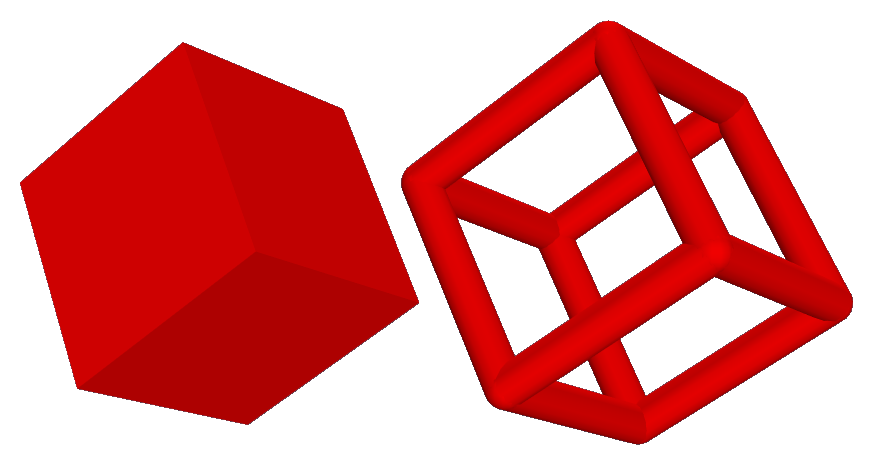
| Figure: | Wire frames with different edge diameter. A value of ~ is used for the wire frame on the left and a value of 1 for the wire frame on the right. |
| Note: | The convex shape generated from the edge data for the shaded graphics view is sometimes a poor representation of the shape. Because of this it may be preferable to specify the wire frame data by panels. |