
|
Vessel data: Shaded drawing |
By default, for shaded 3D views, vessels are drawn using the wire frame data.
The wire frame drawing data comprises vertices and either edges or panels, but OrcaFlex needs a solid surface for the shaded graphics representation. If the wire frame data is specified by panels, then these are used directly to define a surface. This typically results in a good representation of the object in shaded graphics view, and so it is usually preferable to specify the wire frame by panels where possible.
When the wire frame is specified by edges, OrcaFlex uses the following procedure to generate a surface from the wire frame vertices and edges.
First any edges with numerical diameter (i.e. diameter not '~') are drawn as cylinders. This allows you to use such edges to visualise parts of the structure that are not solid, e.g. crane boom latticework. These edges are now handled and are excluded from the remainder of the procedure.
The remaining edges are used to partition the vertices into sets of connected vertices. Two vertices are deemed to be connected if there exists a path of edges between the two vertices.
Finally, for each set of connected vertices, the smallest convex hull enclosing the set is drawn.
This algorithm does not always generate the shaded drawings that you might expect. Consider the following two wire frame vessels. When drawn in wire frame mode they look the same, but in shaded mode they differ.
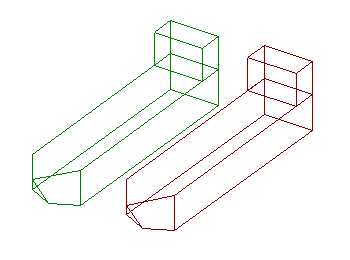
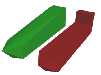
| Figure: | Wire frame and shaded drawing |
For the green vessel the superstructure and the hull share vertices, and so all vertices are connected. This gives a single convex hull. The red vessel's superstructure and hull do not share vertices, so there are two distinct sets of connected vertices resulting in two separate convex hulls and a more appropriate representation.
Alternatively the object can be represented by an imported 3D model by specifying the shaded drawing file. This can be one of the following formats:
If you use a relative path then the path will be taken as relative to the folder containing the OrcaFlex file.
Draw size (.x, .obj) allows you to scale the drawing. All directions are scaled equally such that the longest side in the drawing is drawn to the given draw size. This longest side is calculated by fitting the smallest possible cuboid around the vertices of the shaded drawing, aligned with the shaded drawing's local axes. The longest side is the length of the longest side of this cuboid.
Set draw size to '~' to display the drawing using the absolute coordinates as specified in the drawing file.
| Note: | If you use a value of '~' for draw size, then OrcaFlex uses the coordinates in the drawing file directly, taking them to be in the prevailing OrcaFlex units. If these coordinates use a different length unit from your OrcaFlex model, then you should define them in an auxiliary file called AdditionalInformation.txt. Examples of this can be found in the sample shaded drawings provided by Orcina. |
The culling mode (.x, .obj) option enables an optimisation that may provide a useful performance benefit. When enabled, only faces towards the viewer are drawn. The backward-facing faces are culled – they are not drawn. By culling these faces, less computation is required and performance is improved. In practice however, typical modern graphics cards are sufficiently powerful that you may not notice any benefit.
There are different conventions in common use regarding the specification of the outward facing direction, which we refer to as clockwise or anticlockwise. It is not always possible to detect programmatically which convention is in use, so we must pass the responsibility to you, the user, to do so. It is usually immediately apparent by trial and error which option is correct.
Culling requires that the faces defined in the drawing file have their outward-facing directions defined correctly. If this is not the case, then the object will not display correctly; typically, sections of the the object will be missing when it is drawn by OrcaFlex. This problem is usually resolved by disabling culling.
The mirror in plane (.x, .obj) option allows you to mirror the whole 3D model about the specified plane. Note that the axes refer to the 3D drawing axes rather than the OrcaFlex axes. This may be required if the original drawing axes convention does not match that assumed by OrcaFlex.
These assumptions may not be appropriate for your mesh file, so this option allows you to adjust the rendering so the model appears correctly. When you choose to mirror in a plane, this has the effect of switching from a left-handed axis convention to a right-handed axis convention, and vice versa.
A common sign that the coordinate convention needs switching is if asymmetric features, or text on the model, appear mirrored in the shaded view.
For panel mesh files you must specify the mesh length units and the mesh symmetry. OrcaFlex uses length units to scale the mesh panels to match the units system of the OrcaFlex model. Mesh symmetry can be one of the following values: none, xz plane, yz plane or xz and yz planes. This is used to generate the additional panels that are implied by the symmetry.
For panel mesh files that support multiple bodies or structures, you must specify the body number to be imported. If the panel mesh file format does not support multiple bodies then this value is ignored.
For panel mesh files that define panels above the waterline (dry panels), you must specify whether to import dry panels. If the panel mesh file format does not support dry panels then this value is ignored.
Shaded drawing origin is provided because the shaded drawing and the vessel may have different origins. The shaded drawing origin defines the origin of the shaded drawing with respect to vessel local axes $\Vxyz$. Similarly, shaded drawing orientation allows you to reorient the shaded drawing to match the vessel's axis system.